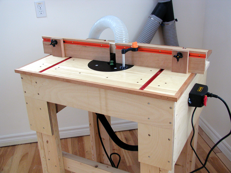
Router table project with integrated Triton 2.25 HP plunge router
 

                       The dimensions chosen for this particular router table are 32 inches wide and 24 inches deep. These dimensions
                       are variable and should be based on your requirements. I have chosen to offset the router insert towards
the
                       front of the table since this is where most routing is performed.
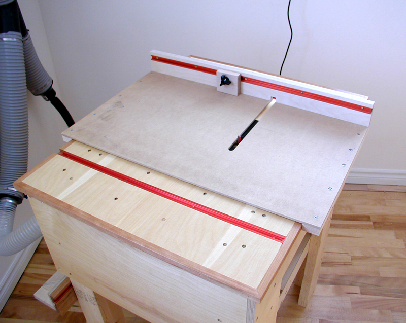
 The design of this table also provides for use of
                       the rear of the table when a larger table surface is required. This is performed by simply flipping the fence around
                       and routing in the opposite direction. I have decided to not incorporate a miter slot and instead will build a router
                       sled to be able to rout at right angles to the table. Another decision was to build the router table top as a torsion
                       box with glued and screwed internal supports or webbing, this to eliminate any possibility of table sag. The torsion
                       box will be very rigid and unable to sag due to its inherent I-beam design characteristics. 

                       There are two 3/4 in. slots on either side of the router which will house 1/4-20 aluminum T-tracks ( 3/8 in. X 3/4in.). 
                       The T-tracks provide the fastening and adjustment of the adjustable fence. The router table top itself is 3/4 in. thick.
                       The inspiration for the router table top and fence originate from an earlier Popular Woodworking article.

                       My criteria for this router table are:

                       - my preferred table height ( 37 inches)
                       - table dimensions which suit the type of work I do ( 32 in. wide  X 24 in. deep)
                       - simple to build, using standard dimensioned lumber
                       - flexibility of fence orientation on table top
                       - good dust collection
                       - ease of accessing the router from the top or bottom
                       - ease of removing router for hand held use
                       - ability to both adjust router bit height and change router bits from top
                       - eliminate possibility of table sag
                       - to incorporate rigidity and mass in table 

                       I chose the Veritas circular router base plate kit to mount the Triton router. This router plate kit has some
                       interesting features such as rigidity, ease of adapting and installing a router to, and can be removed from
                       underneath the table. The low cost of the router plate kit, very good directions for mounting a router,
                       and a small footprint ( 9 inches diameter) of the plate were also deciding factors.


                       Above, after removing the Triton router factory base plate, a clear plastic template is installed on the metal
                       base to begin the process of installing the Veritas router plate. The plastic template is part of the Veritas kit 
                       and along with an included 1/2 inch pin serves as an alignment tool to mark and transfer the base plate holes
                       to the Veritas plate. The router mounting holes are transferred to the template above using a small pin through
                       the plastic template. The plastic template is temporarily taped to the Triton base to keep it oriented correctly.


                       Above, the same plastic template is transferred to the Veritas circular plate along with the 1/2 inch pin and an
                       included washer. The washer is used to center the pin in the new router plate. The pin holes created earlier are
                       transferred to the plastic plate using a pin punch. The marked holes are drilled through using a countersink bit
                       provided with the Veritas kit. This bit also forms the countersink for the router mounting screws.


                       Above, the freshly drilled Veritas plate is temporarily mounted to the router base using the 1/2 inch pin and
                       washer. This centers the Veritas plate on the router bottom. Once centered, a trammel bar is installed on the
                       pin and two 3/16 inch holes drilled on the outer circumference of the Veritas plate. These holes will serve as
                       pivot points for the router when routing out the hole for the insert. You will also notice another hole in the
                       Veritas plate at the top. This 1/2 inch hole allows the above table adjustment tool to attach to the router raising
                       and lowering mechanism. The Triton instructions specify where to drill this adjustment hole on the router plate.


                       Above, the Veritas router plate with all holes drilled and countersunk. To the left are instructions to use the
                       router with the new Veritas base plate attached to rout a corresponding lipped hole in the router table using
                       the small index holes previously drilled on the edge of the router plate. These two holes and the provided pin
                       serve as pivot points for the router. The bolt and rubber sleeve on the edge of the new router plate serve to
                       keep the router plate locked in the table, to keep it oriented, and to prevent any side to side movement..


                       Above, the new router plate bolted to the Triton router. The router bit adjustment hole is also visible along with
                       the locking pin on the edge of the router plate which was mentioned earlier. The screws used to bolt the router
                       to the new router plate are flat topped and recessed to just below the surface of the router plate.


                      Above,  one of the other steps involved in routing out the router plate hole. These steps are well explained in the
                      literature provided with the Veritas router plate. You will also notice the layout lines drawn out on the underside
                      of the table. These layout lines are used for measuring and orienting the torsion box inner frame members.


                       Above, the top of the router table with the router plate insert routed out but still attached to the router table.
                       The 1/2 inch diameter metal pin is inserted in center hole of the router plate mount and is used to pivot the
                       router around to create the router plate recess. The router is pivoted from the small 3/16 in. diameter holes
                       drilled through the outer circumference of the new router plate. These 3/16 in. plate holes fit the 3/16 in. pin
                       at the center of the hole above. The T-slot tracks are also dadoed in at this point. The dadoes are approximately
                       5 inches from the edges of the router table top. These dadoes will house the 3/8 in. deep X 3/4 in. wide
                       T-track aluminum channels.


                       Above, a view of of the 3/4 in. baltic birch router table top table with 3/4 in. dadoes and router insert hole created.
                       The dadoes were created on a table saw with a dado setup. The router table top was run against the table saw
                       fence to create the dadoes. I have taped the hole to keep from damaging it during construction of the router table.


                       Above, the underside of the router table with markings for the individual frame menbers of the torsion box. 
                       The outside edges of the router table will have edging installed once complete. You can also see the larger
                       components in each corner. These are 2X4 leg pairs to hold the table up at approx. 36 inches. There will be
                       a reinforcing skirt around the upper section of the router table consisting of 3/4 inch baltic birch panels.
                       The small routed ears or openings on either side of the router table slot allow the router to be removed from
                       underneath the table.


                       Above, the Veritas router table plate test-fitted to the new router table top. The depth of the router plate lip is
                       critical and the plate should be flush or just slightly below the table top.


                       Above, the Triton 2.25 HP plunge router. This router is ideal for router table mounting and includes the above table
                       router bit height adjustment tool.


                       Above, the router table top now has the T-slot tracks installed. These tracks have been both epoxied and screwed
                       into the router table top.  The spacing of the tracks from the outside edges is critical and should be exactly the
                       same to provide the flexibility of reversing the fence on the router table top. The fence can be reversed to use either
                       the front or rear of the router table for routing. Since the router plate is offset to the front of the table, the rear of the
                       table allows more table area available when routing wider boards.


                       Above, holes have been pre-drilled through the underside for mounting the torsion box frame members. The holes
                       are evenly spaced in this case. The area surrounding the router itself is left open to be able to access the different
                       router adjustments, knobs, and on/off switch. Also, this provides room for router heat dissipation and the below
                       table dust collection I have planned for later. Next I will flip the table top over and countersink the pre-drilled holes
                       for installation of mounting screws.


                       Above, the same holes are countersunk through the router table top. Once the table is completely assembled
                       I plan to fill these holes before applying a protective finish to the table top.

                                                                                           Next Page


                                                                      All rights reserved | Tous droits réservés
                                                                              © 2010 Refined Edge Design    

                                                                                                    
Ottawa Ontario ON K0A 2P0 CANADA
                                                                                      Phone: (613) 821-5160   E-mail:
studio@normanpirollo.com